|
Kostenlose
Laubsägearbeiten Vorlagen 1 |
|
Auf dieser Seite zeige ich Ihcnen eine große Sammlung kostenloser Vorlagen
für Laubsägearbeiten. Ich habe alle sorgfältig gescannt und in pdf-Dateien gewandelt. Die Seiten die die Vorlagen
enthalten, sind größer als A3 (A3 ist doppelt so groß wie die Standard A4 Seite, die die
meisten Drucker drucken können). Das bedeuted, dass wenn Sie nicht einen sehr guten High-End Drucker haben, müssten
Sie die Vorlagen in einem Copy-Shop ausdrucken. Nachdem Sie das einmal gemacht haben, können Sie davon einfache
Fotokopien als Arbeitsgrundlage machen. Klicken Sie einfach auf den Link, um die pdfs der Vorlagen zu erhalten.
These patterns were
published long ago in Hobbies fretwork magazine. They are offered here
with permission of the present Copyright holders, Hobbies Limited. You
can visit their web site here:
http://www.alwayshobbies.com/
Es ware nett, wenn ich Fotos von fertigen Produkten bekommen würde,
um diese Seite zu illustrieren.
Falls jemand einen fehlerhaften oder falschen Link finden sollte,
bitte an info@finescrollsaw.com mailen.
|
 |
|
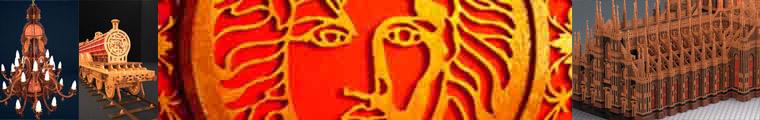
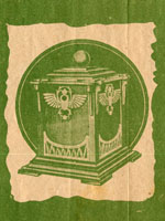
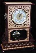
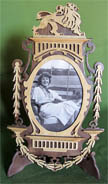
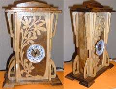
This is the
magnificent rendering of free pattern 1739 by Boris
Radovskiy from the USA: ¨ I made
some modification to original design. I cut
ornaments on the sides for better sound
resonance. All parts connected with slots
for additional durability. And finally, dressed
up with lion's heads and claws for even more
charm and uniqueness. I used walnut and hard
maple and finished with 5 layers of glossy
polyurethane. German made Hermle movement plays
Wesminster chimes. ¨
|
 |
|
Hobbies 2187 by Carlo Saladini from Italy. |
 |
 |
 |
|
Hobbies
1739 von Ali Ajami aus dem Iran. |
Hobbies
2185 von German Loginov aus Rusaland. |
Hobbies
1732 von Loretta Vodziak aus dem USA. |
|
Below follow the original
explanations given in the magazines for some of the patterns above.
|
|
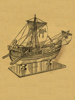 THERE is an ever-increasing popularity for the building of model ships of various
periods, and we have no hesitation in saying that this week's design will be made up
in its hundreds just as the others have been
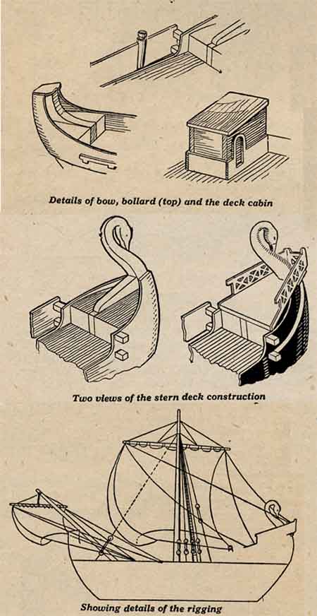
Departing from the usual period of galleons, we have now gone back to the Roman era
of about the second century A.D. The ship illustrated, which can be made from the
design sheet and these instructions, is a Roman merchant ship of that time. These
ships traded between Rome, Egypt and the Levant, carrying corn. It had a capacity
of about 250 tons and was under 100ft. in length.
The actual model we built is a pleasing replica of the actual ship, and follows out
as faithfully as possible the original. One peculiarity, it will be noted, is that
the swan figurehead is at the stern of the ship, and not, as would at first appear,
at the bow. The raised platform in this stern provided the navigator a clear vision
forward over the deck cabin immediately in front of him.
THERE is an ever-increasing popularity for the building of model ships of various
periods, and we have no hesitation in saying that this week's design will be made up
in its hundreds just as the others have been
Departing from the usual period of galleons, we have now gone back to the Roman era
of about the second century A.D. The ship illustrated, which can be made from the
design sheet and these instructions, is a Roman merchant ship of that time. These
ships traded between Rome, Egypt and the Levant, carrying corn. It had a capacity
of about 250 tons and was under 100ft. in length.
The actual model we built is a pleasing replica of the actual ship, and follows out
as faithfully as possible the original. One peculiarity, it will be noted, is that
the swan figurehead is at the stern of the ship, and not, as would at first appear,
at the bow. The raised platform in this stern provided the navigator a clear vision
forward over the deck cabin immediately in front of him.
Sails and Sweeps.
He operated two large flat sweeps to steer the boat, as can be seen in the model.
These sweeps pivoted through the projecting sides, long handles being provided to
reach up to where the navigator stood. There was one mainsail and one forward one
fitted on a bowsprit which passes over the bow, and fits at an angle into the deck.
The boats themselves were very squat in comparison with our present-day streamline
models, being very broad in the beam and almost flat at the bow and stern.
It is this shaping, of course, which will make the actual boat look good in the
finished model, and care must be taken to get the curves nicely
sweeping downwards to the keel and towards the bow and stern at the ends.
Pull size patterns are provided for all parts on the design sheet, and the building
actually is quite simple with a few fretwork tools. The parcel of wood is also
supplied, as well as the pulleys, wire, rigging cord, eyelets, etc. as •well as
the two
anchors which lie on the foredeck with one flange hanging over the side.
The completed model is 11 1/2ins. long and stands 7 1/2ins. high in itself.
A base should, of course, be built and this is arranged for both on the sheet
and in the parcel of wood provided.
Construction of the Hull.
The construction of the actual model is after the same lines as our previous ones.
An upright keel piece in 1/4 in. wood is cut to the shape shown, and on each side of
it are glued the two thick hull pieces A and B. The lower is fin. thick and the upper
Jin. and deal should be used in order to provide soft wood for shaping.
These parts should be glued so that the piece B (the upper part) is in line with the
lowest edge of the sunk portion of the keel. It will be noted that when in place the
keel projects about 1/16in. beyond these hull pieces, and this is as it should be.
Now having glued the blocks in place, take a chisel and a rasp and rough down to the
shape required, taking care to get both sides evenly balanced and symmetrical. Having
got roughly to the shape, finish off with a coarse and then a fine grade of glasspaper,
holding the whole thing firmly in a vice during the operation.
The Main Deck.
Next we can fit on the deck and its position is obvious by the cut fore and aft which
fit over the upright keel pieces. On top of this deck a further block is glued each
side of the keel piece both at the bow and the stern, as can be seen in the details
herewith. The outer edge of these blocks must be symmetrical with the deck and the
hull.
Now comes the main upper sail, and this is cut from very thin plywood then bent round
to the
shape of the hull itself. It is glued in position so the sunk part in the middle is
flush with the top of the deck which should bring the stern rest portion to cover
the stern block. Steam the plywood if necessary to get the correct bend, and pin
it in place temporarily until the glue has set, then nip off the pins flush with
the wood. Be sure to get this plywood close up to the hull, and to the blocks fore
and aft. A good plan is to tie string round and pad it out where necessary with
paper to hold the whole thing until the glue has set. An outer side to the hull
is also provided in this thin plywood. This is the fretted portion, the back end
of which glues to the upper side of the hull. The actual position is shown by the
dotted lines on the latter piece.
The wide or front end, however, does not glue to the hull itself but projects in
order to allow the sweep or guiding oar to pivot through. This again is, shown in
the detail.
Two little blocks A and B of 1/8 in. wood are glued to the hull at the stern end
with just room enough between them for a piece of dowel forming the shafts to the
oars. These two projecting blocks must be glued securely to the hull itself. The
fancy portion of the outer hull is then glued to the other end of them.
The Bollards. About 3/4in. inwards from where these blocks
are glued, comes a bollard. This is a 7/8 in. length of 3/16in.
dowelling. One end is tapered down wedge shaped so it may fit and be
glued between the outer hull and the main body itself. It projects
just over Jin. above the top of the outer side and helps to hold the
whole thing together. Notice the long strip which also has to be
glued to the hull. This is only 1/8in. wide and passes the whole
length. Glue it and pin it to the main hull block 3/16in. below the
plywood side. At the bow end we have a single piece of 1/16in.
plywood glued to the flat top of the keel and to the sides to form
the fancy platform. Against this platform and in the notch provided,
rests the bowsprit, or as it was then known, " artemon." Taper down gradually from 3/16in. dowelling and cut off one end at
an angle to fit the deck.
Deck Cabin.
Of course, if you prefer, you can sink it slightly into the deck itself to glue there
and to the bow platform. On the deck itself is a cabin made up of two ends, two sides
and the roof. The ends go between the sides, and the roof overlaps evenly all round.
All is made of 1/8in. material then round the bottom edge are fitted 1/16in. overlay
pieces.
In these pieces are the two doors, one on each side, and when the whole thing has been
fitted independently it can be glued to the deck close up to the stern blocks, and
with the roof sloping forward towards the masts.
Sweeps.
The oar pieces can next be made, and a detail of one of these is given on the design
sheet. When complete it is put through between the two little blocks A and B with the
handle projecting about 1in. It is fixed by means of a nail carefully driven through
the outer plywood into the main hull itself. Before doing this, however, fix an arc
of brass wire leading from the handle of the oar to the centre of the roof of the cabin.
This represents the handle which the steersman used when standing on the stern deck.
This stern deck is actually a raised piece of
1/8in. wood which fits over the swan head, and is glued to the top of the plywood
sides as well as in the corner of the cabin and stern deck itself. The edge to this
raised and sloping stern deck is provided in fancy rails. Glue the side ones then the
stern one over the ends.
The Mainsail.
The mainsail is added by means of a long cross spar which is tapered towards each
end. A sail to the bowsprit is added in a similar way, and parchment is supplied
for both these pieces. The animals indicated by the outline should be painted
before the sails are added.
They are fixed by means of the cord being twined through at holes about fin. apart,
then the rigging is fixed from the mast to the spars and so down to the deck as can
be seen in the drawing of the finished model. The deck has little eyelets to hold the
ends of this cord.
Painting Plan Provided.
The whole model should be finally cleaned up with glasspaper then painted. The hull
has a light natural grain with a darker enamel used on the main pieces of plywood.
The decoration of the rails is painted white. The deck is stained light then varnished
over and lined for planking. The cabin also is painted in two colours. The overlays and
roof are buff, and the main body brown. The stern sloping back can also be buff
colour, whilst the swan head is white with suitable eye and beak.
A detailed drawing of these colourings is obtainable on request from the Editor
if you enclose 3d. in stamps.
Little pulleys are provided in the rigging, and 20 of these are required. Four lines
of ropes to the deck are trailed up to the masthead, whilst a rope ladder is fitted
from the deck between the cabin and the mast. A further rigging with two pulley blocks
is drawn from the masthead to the bowsprit base or about 1/2in. upwards from it.
It is a good plan, by the way, to shape off the swan's neck at the stern by rounding
the parts slightly to give a more realistic finish.
The Base.
The base is a piece of fin. wood preferably mahogany or some fancy wood, 3 1/2 ins.
wide and 8ins. long. Then 1 1/2ins. from each end on a centre line, two fancy turnings
should be fixed in. These turnings are supplied as a complete finial and it will be
necessary to cut off the top tapering portion as shown on the design sheet. Cut this
off flat first, then fit in a groove to take the keel of the boat which should rest
firmly and steadily in place.
|
|
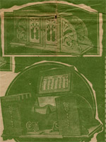
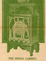
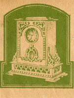
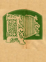
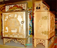
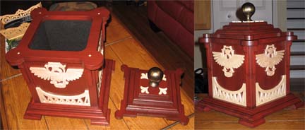
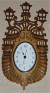
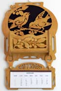
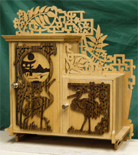
 THIS full size gift design this week is for the making of a handsome and useful
Japanese type of cabinet which is always so popular both with workers and with
the owners.
The cabinet, as can be seen, is a handsome one, and is quite large enough for
ordinary general use. It is just over a foot wide, 13 1/4ins. high and 4ms. deep,
and the fancy work on it is typically Japanese, the flowering being of the plum
and the bird features the Japanese crane. There is not, however, a terrific amount
of fretwork to be undertaken, for the sides and main portions of the cabinet are
solid pieces and so are easily cut and fixed.
Really there are two cabinets—one tall one with a mirror, the other a shorter one
of almost cubic dimensions. Thus there are two doors to be fixed and two
compartments provided for the small everyday articles.
THIS full size gift design this week is for the making of a handsome and useful
Japanese type of cabinet which is always so popular both with workers and with
the owners.
The cabinet, as can be seen, is a handsome one, and is quite large enough for
ordinary general use. It is just over a foot wide, 13 1/4ins. high and 4ms. deep,
and the fancy work on it is typically Japanese, the flowering being of the plum
and the bird features the Japanese crane. There is not, however, a terrific amount
of fretwork to be undertaken, for the sides and main portions of the cabinet are
solid pieces and so are easily cut and fixed.
Really there are two cabinets—one tall one with a mirror, the other a shorter one
of almost cubic dimensions. Thus there are two doors to be fixed and two
compartments provided for the small everyday articles.
The Wood to Use.
There is a wide choice of wood for such a piece of work as this, and any of the
ordinary fretwork boards such as oak, beech, satin walnut or white-wood are
suitable. The parcel supplied by Hobbies contains whitewood and satin walnut,
and details of this and of the usual fittings are given herewith. The mirror,
hinges and catches for the doors are also supplied quite reasonably, as shown in
the Materials list.
The construction of the cabinet is quite straightforward, but it will be
necessary to study the design sheet first to get a good idea how the
patterns are worked out. We then go a step further and add the framework of the two cabinets on to
the back itself. Finally, of course, there are the doors to add, as well as the
fancy edging and little ornamental piece on the top of the smaller cabinet. It will be noted that several of them are shown on the design
sheet and broken in two, and with merely a dimension showing the exact size of
the
part. This saves a considerable amount of room on the sheet, and otherwise we
should not have been able to give you such a large cabinet.
Notice the dimensions which are given between the arrowheads concerned, then
extend the two patterns on to the actual wood. Paste one end down first, carry
out a pencil line along the edge far enough to allow a second piece. Paste this
second piece down so it is in line with the first, and the two edges required are
the proper distance apart.
The Doors.
In the case of the doors, these are plain rectangles, and there is really no need
to paste the actual patterns down. Measure the parts out carefully and mark them
straight on to the wood ready for cutting out.
All the parts in connection with this cabinet must be very carefully fitted because
in most
cases they are butt joints and if there is any gap between them the whole thing
will look unsightly.
In addition to the butt joints concerned, the various rails are fitted by means
of dove tails, whilst in the case of the partition and the left side of the cabinet,
mortise and tenon joints are fitted to hold the parts more firmly. Again, the floor
of the cabinet is fitted to the sides by halving joints, so that altogether we have
a variety of joints in the article which will prove our ability in carpentry and
fretwork.
First of all get out the upper part of the back and fit into the two dove tails at E,
and F, the left and right side rails. They are held across the
the top of the cabinet and the partitions. The top of the smaller cabinet has a plain
rectangular piece which goes above the upright side. The top of the larger cabinet has
the two mortises at C and D to fix on to the left-hand side, and the centre partition.
Assembly.
The whole framework of the cabinet can now be laid in place on the back, and when ready
can be there glued and nailed. The top of the larger cabinet has a shaped edging. Cut three pieces of edging from 3/8in. wood to the dimensions and
shapes shown, then with a plane chamfer down the under edge.
Be careful not to carry this chamfer quite to the top edge, but leave about 1/16in.
thickness to prevent breakage. The doors, too, need some attention before they are
actually fitted in. The larger one has the circular mirror laid in the opening cut,
and held there by the fancy overlay cut from 1/16in. wood.
Remember, of course, to nail thin wood like this to a thicker piece to provide
greater strength during cutting. The smaller door has a plain overlay on with the
crane facing in the other direction.
Door Fittings.
Both doors are fitted with a little catch and if necessary a stop is put behind to
prevent them swinging inwards too far. The hinges are fitted at the right-hand edges
and to the inside surface of the appropriate sides.
So far a portion of the back has a hollow aperture, and this has to be filled by a
piece of plywood 7 3/4ins. long and 3 1/2ins. high. It should be cut to fit
bottom by a cross rail which fits in at G and H. Get all these to lie firmly in
each other and be perfectly flat together. Glue and weight down until set.
In the meantime you can be getting out the framework of the cabinet itself. This
consists of the two tall sides and the short side, all of which are fitted between
the long floor piece and the top to the large and small cabinet.
The Sides.
Into the floor itself is halved the two sides at A and B. Notice these sides are
longer than each other, one being 9-7/16ins. and the other 6|ins. between the
arrowheads marked on the pattern. Between these two uprights is the partition
8-3/16ins. long with a tenon (D) at one end. It is advisable to cut out the doors
themselves before
fixing this partition or the top to the cabinet, because they will help to give
the correct positions of these parts.
There is no need to finish the door off entirely, but merely to cut it out to the
outline, then use it to fit up to
into the aperture of the two side rails, and the top and bottom lying long ways.
It is affixed by putting in a little fillet strip in the thickness of the back, or, of course, a strip can be glued along inside and the backing
piece put up to it. The wood, of course, can be cut from any of
the waste material of the other parts. If the cabinet is finished in whitewood
there will be no need to stain it or colour it, but, the overlays should be cut
in some distinctive material to make them stand out from the rest. Brass hangers
should be put on to affix it to the wall—do not allow the weight to go on to the
delicate frets. |
|
 PICTURE yourself going on holidays a hundred years ago. Think of the joy (?) of
lumbering along in a heavy, almost springless stage coach at a few miles an
hour, and stopping at the coach-houses to give the horses a rest or to change them.
Think of the excitement and dread of highwaymen, of the dark coach interior
and of the uncertainty of arrival.
Those days are happily over, and our connection with them is largely in spirited
tales or visiting coaches occasionally found in museums. The days taken on the
journey then have been turned merely into hours now. Letters arrive by fast train
for the next morning's delivery, which took possibly a week when these good old
coaches were trailing along the flinty and dusty highway.
PICTURE yourself going on holidays a hundred years ago. Think of the joy (?) of
lumbering along in a heavy, almost springless stage coach at a few miles an
hour, and stopping at the coach-houses to give the horses a rest or to change them.
Think of the excitement and dread of highwaymen, of the dark coach interior
and of the uncertainty of arrival.
Those days are happily over, and our connection with them is largely in spirited
tales or visiting coaches occasionally found in museums. The days taken on the
journey then have been turned merely into hours now. Letters arrive by fast train
for the next morning's delivery, which took possibly a week when these good old
coaches were trailing along the flinty and dusty highway.
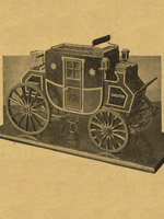
An Historic Model.
The old coach is a picturesque reminder of old times, and certainly forms a
very novel subject for the model maker. Here you have the opportunity of
completing a very realistic one of the Holyhead Mail which actually ceased
running exactly 100 years ago.
The model completed would catch the eye of anyone, and actually it is one of
the simplest we have yet published for making and finishing. Look at the photographs
of it herewith. Doesn't it really stand out and catch your eye? Wouldn't
it be just the thing to enter in an Exhibition, or to hold as a sort of museum
piece on the sideboard? Nicely painted in the proper colours, it stands up
very strongly and anyone with a few fretwork tools can complete it.
As usual, we have put the patterns full size on the design sheet, and have
published one double the usual size in order to provide every facility for
the worker. Moreover, all the necessary parts are supplied in a complete parcel.
There are the planed boards in the thicknesses required, the various little
spindles and dowel pieces, the special wire for the seat edging, carriage racks,
steps, etc. and the thicker undercarriage metal for footboard and axle.
Thus it is essential to get this parcel right away and study the various parts
in conjunction with the design sheet.
There is actually very little interior work to be undertaken, and in order that
we may have the design pattern for reference, it is best to trace out the outlines
direct to the wood. This can be done by laying the pattern sheet over the board
with a piece of carbon between the two. Then by going over the outline, you get
the shape needed.
This is much better than pasting the actual patterns down, because there are
several other points on each showing you other positions.
A further convenience is that all the parts are
lettered on the sheet, and wherever possible these letters are shown on adjoining
pieces. For instance, the framework of the coach is made up of the two sides and
a number of pieces going between. The position of these between pieces is shown by
the letters, and dotted lines round the edge of the pattern of the sides.
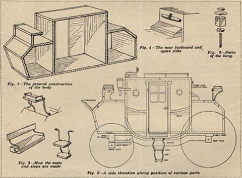
The Coach Carcase.
The illustration at Fig. 1 is a detail of how the main coach is built up, but one
of the sides has been purposely omitted to show the various parts. The floor and
roof can be put between the two sides first, then the other pieces A, B, C, and
so on.
You will notice, of course, that the ends of several of these pieces have to be
chamfered in order to get them to fit snugly against the others, and a reference
to the elevation at Fig. 2 shows
and over this is put on the overlay. The door is cut and fitted with a piece
of glass.
This glass lies in the aperture of the main door, is held in from the front by
the overlay and fixed at the back by matchstick-like strips glued along the edges.
The door is hinged in two places with a pair of fin. hinges let into the edges of
the wood and opposite the hinges is fitted the little brass knob with catch
supplied.
Inside the coach are two cross pieces forming seats, and it will be noted that
the actual side drops below the floor some distance (see Fig. 2).
There are numerous additional pieces to add to form seats, footboard, lamps,
etc. A back seat is fitted up on brass wire and a detail of this is given at Fig. 3.
In the same detail one is shown how to make up the coachman's and the roof seats.
The uppermost one—on the roof—is built up
this quite clearly. This detail is also quite helpful in general construction and
should be watched through at different points.
Where the cross pieces project they need not be chamfered until the whole carcase
is together, then they can be cut off with a plane or chisel. The whole outer
surface of the coach so far as the cross pieces are concerned is flush.
All this work can be done temporarily, but before the sides are actually put on
they should be built up with their overlays. To form the " bulge " the outer
side in 3/16in. thick is added,
of two 3/16in. pieces. Glue them securely together, then to the roof of the
coach flush with the front edge. A back is fitted by means of the brass wire,
as shown in Fig. 3. Just below and in front of this is the driver's seat raised
a little higher than the one beside him (see Fig. 3).
Cushions and Footboard.
Piece E forms the cushion part, with another 3/16in., rectangle glued to it at
one end to form the driver's seat which, remember, is always on the right hand.
A footboard is provided for the rear seat at the back of the coach by two pieces
of 3/16in. wood glued together and shaped by a chamfer slope (see Fig. 4). These
are the widths of the coach only and do not extend to the side overlays.
The top of the coach is wired up with brass wire as can be seen in the detail
of the finished model. All this brass wire is easily bent with small pliers.
The end of each piece should be filed to a sharp point if it is to be driven
into the wood.
If, on the other hand it is to be fitted on the outside, then the end is
beaten out flat and a tiny hole made to take a small screw or round headed fretnail. The special wire supplied is quite suitable for the job.
Wire Rails.
The brass wire is for all these seat fittings, whilst the iron wire of a
thicker gauge is to be used on the undercarriage stays as will be shown.
Each side of the coach is decorated by two stars, and these are cut from
thin wood. They can be glued on now, or perhaps it would be better
the top is fitted an overlapping rectangle with shaped edges, and above
this in turn is a circular capping piece. On the underside of the lamp a
hole is bored into the fin. piece to take a short length of 1/8in. dowel to
form the spindle. This dowelling is let into the wood about 3/16in. The spindle
itself is 1 1/8in. long with the lower end rounded off. Glue it into the
underside of the
to leave them until the body is painted, then fixed afterwards.
The footboard for the coachman is a plain rectangle fitted sloping from the front.
The angle of the slope can be seen from Pig. 4, and the fixing is done by two metal
strip pieces bent as shown on the design sheet and screwed to the sloping front about
Jin. inwards from each end.
Lamps are hung to each of the front corners, and the bracket is glued on to the
angle 1in. downwards from the top. The lamp itself is made up of fin. square of
wood fin. long. On
lamp, then push up one of the little overlay rims shown. All these parts are shown
in Fig. 2 ready to put together. The lamp, of course, is just hung into the bracket
fixed to the coach, The steps to the coach are also shown in detail at Fig. 3.
Two pieces of wood are connected up by the brass wire, the top ends of which are
turned under the side of the coach and there screwed in place.
{To be Continued) |
|
 THIS week we have pleasure in adding another of the famous old-time sailing ships
to the range which have already appeared in these pages. Everyone knows of
the exploits of Columbus and his discovery of America. Well, this is the
type of ship in which he undertook the hazardous and unknown journey across the
Atlantic. The " Santa Maria " has gone down in history as much as the name of
Columbus himself, and the model shown always proves popular. These models
are not usually simple to make because of the various parts which have to be cut
and shaped, but with the aid of the pictures herewith, and the full size diagrams
on our design sheet this week, the work is quite straightforward. THIS week we have pleasure in adding another of the famous old-time sailing ships
to the range which have already appeared in these pages. Everyone knows of
the exploits of Columbus and his discovery of America. Well, this is the
type of ship in which he undertook the hazardous and unknown journey across the
Atlantic. The " Santa Maria " has gone down in history as much as the name of
Columbus himself, and the model shown always proves popular. These models
are not usually simple to make because of the various parts which have to be cut
and shaped, but with the aid of the pictures herewith, and the full size diagrams
on our design sheet this week, the work is quite straightforward.
Tools and Materials.
The use of the fretsaw, of course, is essential, as ordinary fretwood is used
throughout. Apart from that, however, the work involved is in shaping the hull,
and fixing up the rigging and finally painting the whole model.
By following these instructions in conjunction with the patterns, however,
and using the special parcel of wood supplied, the matter is all comparatively
simple. Do not, however, be in a
hurry with any of the parts. Finish them off carefully, take your time in the shaping,
fitting and gluing, then finally add the paint carefully.
First of all get the parcel of wood supplied, because here you have
all the necessary planed boards, as well as the pulley blocks, the
dowel rod for masts, and all the necessary cord for the riggings. This
overcomes the trouble of planing the wood down and cutting it out to
the necessary dimensions.
But before commencing work, a note or two on the actual boat may be of
interest.
Interesting Historical Notes.
The " Santa Maria " is the famous flagship of the squadron of three vessels
led by Christopher Columbus during his famous voyage of 1492. He discovered
various islands, but unfortunately in the end his ship went ashore on what is
now known as Hayti, and was abandoned.
The fact that she was never refloated makes records of her a little difficult
to follow, but it is known that she carried one cannon and one boat only, and
her officers and crew totalled 38 to 40 persons.
The model we show is a replica as far as possible of the actual boat, although
naturally it is impossible to add all the small and minor fittings built on the
prototype. Our model is 16 1/2ins. long and 15ins. high.
Now let us look at the design sheet and commence the work of construction. First
of all, get a general idea of how it is built and notice the various dotted lines
on the patterns illustrating where adjoining pieces come. Indeed, it is a good plan
to have a second sheet so that when the patterns are used on one, there is still a reference which can be made to the other.
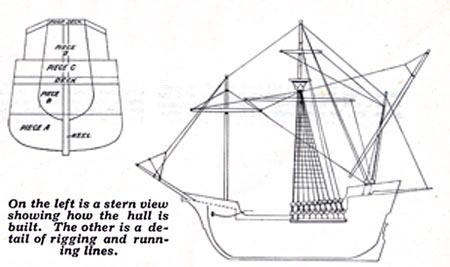
The Hull Construction
The hull itself is made of a centre upright piece (the keel) on each side of
which are added the deck—halved in fore and aft—and the thick pieces A and B.
Glue these all in position then round them off to a nice shape as can be seen
by the pictures.
A stern view is given which is helpful also in
this respect. Neither the deck nor the thicker pieces, it will be noted, go to
the extreme edge of the upright keel piece.
To get the raised stern and fore-deck we add further blocks (C, D and E). Two
pieces of fin. stuff (C) are cut and glued to the deck and the centre keel, so
that the outer edge is flush with the hull.
This piece is in line at the stern with the deck itself, and slopes inwards and
downwards as indicated in the pattern of the keel.
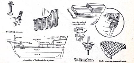
Stern Deck
Above this conies the piece D from 1in. stuff. This projects a little beyond the
other part, as can be seen on the same pattern and in the further detailed drawing
given. Let us finish this stern deck construction first before going forward. The
front projecting portion of part C provides a floor for the quarter-deck, which
is a piece lifted above the main deck and projecting beyond part C.
Then to the front of the upper portion (D), the front of the poop deck part is
cut. This is shown with dotted arched lines on it, and these indicate the
doorways and openings which are painted on the complete model.
Now add the poop deck itself on the top of block B, noting that it slopes
upwards gradually to the stern, and parallel to the keel portion.
The Bow Details.
We can now transfer our attention to the fore-end and add the two blocks E. Note
how they are shaped according to the section, the front edge being fin. thick
tapering down at the back to fin. The outer edge is the same shape as the hull.
Before going further it is advisable to add the overlays forming the ornamental
sides. These upper sides are cut from 1/16in. plywood, one piece to outline only,
then one piece with its fretted work being glued on top.
Cut out the fretted piece first—the two sides can be cut together—then glue them
on to the
piece of plywood of the side. Now cut the outline complete, and you have both
parts exactly alike. Notice there is only one gun, and in consequence a hole
has to be made in one side only. The completed side is now glued on, bending it
carefully round to the shape of the hull. It stands above the deck on its whole
length, and can there be temporarily tacked in place until we are sure we have
got the other pieces on the fore-deck correct.
In the front end of these sides there are slots which coincide with the slots in
the centre keel portion. These are to take the cross strips which come on the
underside of the forecastle deck.
Glue these strips in place, the longest at the back, then on the top of them
glue the forecastle
deck. A detail of this is shown upside down herewith to show exactly how it is
constructed. The sides to this deck are plywood pieces glued over the edges of
the actual deck, and forming the rail to it. On the extreme front there is the
little peak piece which is glued carefully between to take the bowsprit. Hold
this piece off for the time being, because it will be easier to fit in at the
same time as the bowsprit itself.
Strips and Channel.
Returning to the sides, we have to add these tiny upright strips which are glued
to the fretted pieces. Various lengths of these are required 1/8 in. thick. They
form ribs and two of them are shown as an example on the sheet whilst a detail of
them is given herewith.
They are glued to all the upright pieces, stopping short about 1/16in. from the
top and bottom, and tapering gradually about 1/4 in. from each end. The length of
these can be measured from the actual model, and the pieces then glued in place.
The channels which hold the ends of the ladders are fitted to each side projecting
outwards from the hull.
The sails are fitted to the spars with glue, and the running cord leading to
the various points shown in the drawing.
A crow's nest is added to the main mast, and this is built from two pieces as
shown in the accessories. How the lantern is made up for the stern is also shown
here, as well as a drawing of the finished article painted.
The ladders, or shrouds, are fitted to the main mast just under the crow's nest
spreading out to eight sets of two pulley blocks which in turn lead down to the
channels on the side.
A couple of anchors are added, and these lie on the deck, being strung to the hole
in the bow at the position shown.
Painting.
When complete the hull is painted a dull brown, and the deck lined for planking
in pencil. The lower portion of the hull is white, whilst the overlay strip on the
sides are buff or cream. The mast can be plain varnished, and the stern and fancy
decoration on the sides is treated in gold.
There are, of course, several flags to add, and the long pennant strips which can
be seen in the
The shape of these pieces is shown on the sheet, and the small hole is made in each
of
the points shown to take the cord later. To the upper stern is added a fancy overlay
in 1/16in. wood.
On the deck there are two steps, F and G. These are cut to the shape shown, and have
to have the ends chamfered to allow them to stand on the main deck, and fit close to
the front of the quarter-deck and the poop deck. The steps themselves are painted on
by lines run across.
So far as the masts, sails and rigging are concerned, the drawings herewith show the
positions and details of these clearly. It has been impossible to show full size
patterns of the complete sails, but as half of them are given full size, it is easy
to duplicate that portion and complete the work.
The Sails.
The sails are cut from parchment paper, then bent to the shape shown. The masts
must be tapered upwards, and the cross spars towards each end.
picture. All these can be cut from paper and suitably painted up. The mainsail
and foresail each have the cross painted in red upon them. This should be done
before the sail is bellied out.
A Base.
The whole model can be stood on a simple base. Cut a piece of fretwood 10 1/2ins.
long, 3 1/4ins. wide and fin. thick. Round the edges slightly, then add two cross
pieces about 4ms. apart to take the shape of the hull itself. This base should be
made in nice fretwood, stained and polished up to complete the job.
|
|
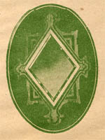
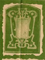
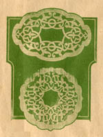
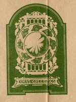
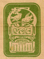
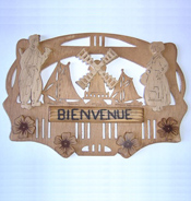
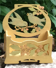
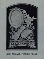 IN continuation of our Overseas Series of designs we are this week publishing one
which will particularly appeal to our readers in New Zealand, and workers
in other countries who have friends in the two islands
"down under". The style of the Photo Frame is quite clear in, the picture on this
page, and the subject is intended to form a companion to the Australian frame which
was issued as Design No. 1642.
IN continuation of our Overseas Series of designs we are this week publishing one
which will particularly appeal to our readers in New Zealand, and workers
in other countries who have friends in the two islands
"down under". The style of the Photo Frame is quite clear in, the picture on this
page, and the subject is intended to form a companion to the Australian frame which
was issued as Design No. 1642.
Characteristics.
As in the other designs of this series, distinctive features of the country are introduced. In the New Zealand frame herewith, we have a background containing a
very distinct outline of the North and South Islands, in which the various counties
are marked off. The fretwork holding this chart together is composed of creeping
clematis, a flower which ranks as one of the favourites in New Zealand. Then as
an overlay we have the kiwi, which is indeed a feature which could not be introduced
into any other country's characteristics.
The Quaint Kiwi.
The kiwi is peculiar to New Zealand and is indeed peculiar to itself. Its feathers
are hair-like in appearance, and it is apparently without wings. It lives on worms
and is nocturnal in
its habits. Unfortunately, the bird cannot be reared in captivity, and in
consequence, is gradually becoming extinct, although now carefully protected. The overlay feature of this bird in the design stands upon a little projecting ledge, and beneath this in turn is an overlay bearing the words " New Zealand." So altogether we make up quite an interesting and appealing piece of work. The cost of its making, too, is quite reasonable, the complete parcel of wood being only 1/6. Further to this, we require just a piece of glass and a hinge, as detailed at the end of this article.
Work In The Back.
The back of the frame itself is cut from a 3/16in. panel of mahogany, whilst
overlays
are 1/8-in. thick and cut from bright yellow satin-wood to form a contrast. The
frame itself contains little that need worry us so far as
cutting is concerned, and as it is taken from 3/16in. board we can quite well cut
out the outline 'first. The shape of the clematis is a six petalled flower, and we
must note to keep these almost alike in their complete shape and in their independent
parts. The links which hold the various parts of the design together have been kept
as small as possible commensurate with sufficient strength to hold the whole
together.
The frame holds a picture 5 1/2ins. high and just 4ins. wide. If we are using
the oval piece cut from this frame as a backing board, remember to make the
drill-hole on the cutting line. As. however, this thickness behind the glass
and picture causes the board to project beyond the face of the rest of the
wood, we can quite well throw away this piece and use a piece of thinner
material—either wood or card— as backing.
A Word About Sandpapering.
When the work of cutting has been completed, let us straightway clean the
part up. Sandpapering is never a pleasant job, but it has to be done.
Better, therefore, to do it now than to put the piece on one side until we
have some more. If all the parts have to be cleaned up together, we shall surely
get tired of the operation, so it is best to clean each part as soon as it is cut.
The work of sandpapering is as essential as that of cutting the designs, and if
a fine grade of sandpaper is used to finish off with, the wood will have assumed
a semi-glossy appearance which brings out quite clearly the grain of the board.
Marking The Counties.
By the way, in cutting out this back, you will note that the counties of the
two islands are indicated merely by long narrow lines. These, of course, can be
cut out with the fretsaw in the ordinary way, but as such work will necessarily
weaken the complete frame, we would recommend the use of a V tool or knife, so that
a groove is made into the wood rather than an actual piece cut out. These recessed
lines can be cut deep enough to make the markings quite clear, and we can even,
if necessary, make them more distinct with a line of colour satin.
Overlays.
There are four overlays which we have to undertake, but none of them has any
intricate detail to worry over. The one with the greatest amount of work is that
containing the words "New Zealand." The outline - of the letters is our chief
consideration, but if one
follows the cutting-line given and notices the continuity of the words as they
are being formed, one cannot go far wrong. It is a good plan to run a pencil-line
along the top of the letters from one end to the other. This will help us to keep
the saw in alignment the whole length. Notice, too, the thick and thin stems of
the letters, and see that they are even in each one. That is, if the stem is thick,
do not cut it down until it is equal to the thin stem. Neither should we leave the
thin stem wide enough to make it look a thick one.
Two Single Parts.
The overlay of the bird itself has no real interior fretcutting at all. The
peculiar markings of the feathers, the line of the beak, and the opening of the
eye can be cut as before with a V tool or knife and when these have been
completed the outline can be taken away. There is only a narrow neck of wood
through the beak and the legs, so that we must hold the board firmly on the
cutting-table and close to the saw blade, using a saw which will cut clean and
without pulling.
Finding Positions.
The other overlay is a plain elliptical rim, cut so that it fits over the opening
in the back evenly all the way round. The three overlays are ready for fitting,
but in the case of the one of New Zealand, its position is ruled by the narrow
ledge which is fitted below the kiwi itself.
Glue on the bird so that its outline is identical with that in the. back. Then
put the ledge with its rounded edge outwards so that it fits in line with the
lower portion of the frame. The position of this ledge too rules the position
of the overlay of the words New Zealand, for this part is pushed up to it when
glued in place.
Making A Support.
The only remaining part to cut and fix is the strut. This has a long chamfer
to its top edge and it is hinged (by Hinge No. 5 364) to the back of the
centre-piece of the oval frame. The position is ruled by the slope of the
frame itself when the strut is open, and where it is fixed is shown by the
sectional drawing on the design sheet. This drawing also gives us the detail
of the frame and the overlay which holds the glass and picture in place.
The drawing is the section cut through the centre of the oval frame.
|
|
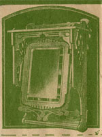
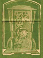
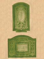
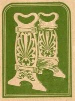
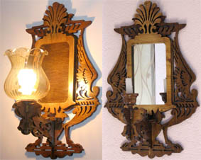
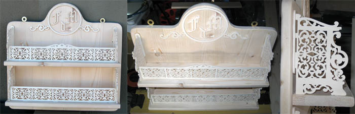
 THERE are a number of our readers to whom the cutting of lettering and the making
of mottoes is always fascinating work. They will be particularly pleased,
therefore, with the opportunity given with this week's Design where two Wall
Texts are provided for their cutting. To make lettering in wood we must
be fairly expert in the use of the saw, but there is no doubt that once having
acquired the art, an endless variety of work is opened up to us. The range of
mottoes illustrated in the current Hobbies' Catalogue proves the popularity
of this class of work. Although the actual design of lettering need not be the
same, the work thereon follows a general principle right through. The letters
must be so cut that they stand out quite clear and sharp from the design, but
at the same time must be
made sufficiently strong to hold together in the completed part.
THERE are a number of our readers to whom the cutting of lettering and the making
of mottoes is always fascinating work. They will be particularly pleased,
therefore, with the opportunity given with this week's Design where two Wall
Texts are provided for their cutting. To make lettering in wood we must
be fairly expert in the use of the saw, but there is no doubt that once having
acquired the art, an endless variety of work is opened up to us. The range of
mottoes illustrated in the current Hobbies' Catalogue proves the popularity
of this class of work. Although the actual design of lettering need not be the
same, the work thereon follows a general principle right through. The letters
must be so cut that they stand out quite clear and sharp from the design, but
at the same time must be
made sufficiently strong to hold together in the completed part.
Two Methods.
There are two distinct methods of cutting letters in fretwork, and we have an
opportunity of using both in the two designs offered on the Design Sheet. In
one case the motto is composed of each letter being cut out separately and glued
to a solid background. In the other
case we have the letters cut as a complete motto forming a portion of an overlay
and glued as a whole to the background piece. Both operations call for distinct
ability, and the beginner must not be disappointed if he spoils one or two letters
before he becomes able to complete the work satisfactorily. To make a satisfactory
piece of work, the motto itself should stand out in high relief from the background,
and should,
therefore, be cut in a wood contrasting as much as possible from the part behind it.
Almost any popular fret-woods which cover this point can be used, but the parcel of
wood supplied by Hobbies contains mahogany for the background, and whitewood
for the overlays. This is material suitable to the work in hand, and at the
same time easily cut and manipulated. The size of the text can be gleaned by
a glance at the Design
Sheet, whilst the finished work is illustrated on our cover and this page.
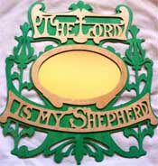
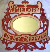
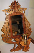
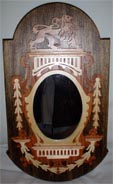
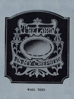
The Overlay Text. The text " A " contains its wording in two
portions, but both are cut in the same manner, and each from a
single piece of wood. " The Lord " is cut as one part, and " is my
Shepherd " appears as a second line below the mirror. When the back
has been cut and cleaned, we can proceed straight away to the text itself. The ordinary rules which we apply in
cutting are followed out in these parts, but instead of the ordinary fretwork
we have here definite letters. These letters stand out quite clearly if cut
correctly, but if any of them are misshapen or drop out of their correct
alignment, the complete text seems to be spoiled. Let us, therefore, pay particular
attention to the line-work of the motto, and adhere strictly to the design
given. When the mottoes are cut they are cleaned up and laid aside ready
for gluing.
The Mirror Overlay.
The only other overlay is the one to hold the mirror in place. Prom the centre
of this is cut "The Lord," required for the other text, but as both parts
are in the same thickness, the whole design can be pasted to one board. So far
as we are at present concerned, we only want the rim which forms the overlay
for the mirror, and with this cleaned up, the three overlays are glued on to
the back. The dotted lines given on the pattern on the Design Sheet will, of
course, have disappeared in the cleaning, but the outline of the work itself
should be sufficient indication of the actual position of the overlays. They
are glued centrally in the space allowed for them, with the mirror overlay
between. This overlay projects evenly round the aperture in the back, so as
to hold the mirror in position. The piece which was taken out from the back
can be replaced to hold the glass in place, or the aperture can be filled
up with cardboard or blotting paper. As the mirror is not likely to be taken
out again, it is best to paste a piece of brown paper over the whole lot instead
of having photo clips.
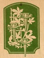
Independent Lettering.
The other motto text—" Rest in the Lord "— is taken from only one piece of
wood, and beneath the text itself is a spray of madonna lilies. In the other
text the wording is incorporated in the actual overlay, and between the two parts
is fitted a beveled mirror. It is immaterial upon which one we begin, but
in all cases the paper should be allowed to dry upon the wood before we commence
to cut it. In both cases, too, we should start by getting out the back,
and in neither instance is there a great deal of work to take up our time.
In the case of the text " B' ' we must arrange to mark on the position of the "
Rest in the Lord " lettering before the paper is cleaned off, otherwise we
shall have no guidance where to put the words. The best method is
to run a pencil-line along the top of the bottom of the letters, as indicated
by the dotted lines on the Design part. Then prick through each point where the
top of the letter touches this line. Use a proper pricker or a sharp-pointed
nail. Take care that the hole is not made too large or outside the line.
Having made this series of dots, we can clean off the design paper and yet
be sure of getting the letters glued down in the right position. The sawdust
may have been sandpapered into the holes made by the pricker, but this is
easily tapped out so that the position is discernible.
The Greatest Needs.
The cutting of the lettering itself calls for patience and ability. The
motto is cut in 1/8-in. wood, so that it will be quite delicate across
some of the narrow necks of the letters. Let us, therefore, get out the
interior work of the parts first, and be careful to hold each letter very
close to the saw blade as we go round its outline. Use a sharp saw of a
fine grade, and do not let the wood jump off the cutting-table. The cleaning
of these tiny pieces will also call for great care, and we can, perhaps,
obviate the likelihood of breakage by using the waste wood as a frame in
which to replace the letters while they are being cleaned.
Points in Cleaning.
In any case, see that they are perfectly flat, and use a fine grade of
sandpaper. Take longer than usual in cleaning all these parts, rather
than rush the work and damage some of the delicate pieces. When all the
parts are cleaned and the burr of the saw taken off the back of the wood
also, the letters can be glued down in their proper position. Do not put
too much glue on their surface, but cover the whole of it thinly to hold
each part of the letter down firmly. Put the letters down as quickly as
possible, and have a piece of wood ready to lay over the whole of their
surface, so that a weight may be added to keep them flat until the glue
has set. Be careful in putting this cover-piece on, not to move any particular
letter, or it will necessitate forcing this one off again and re-cutting later
on.
|
|
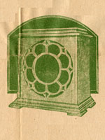
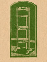
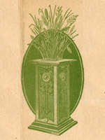
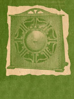
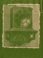
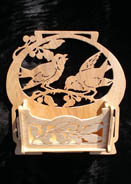
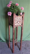
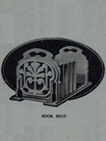 THIS week we have the Design for making up a simple Book Rest, and as the illustration shows, it is a piece of work which would be acceptable
to anyone. The Book Rest illustrated is planned with its two end panels
in Antofret, but it is so arranged that these panels can be cut in
straightforward fretwork if so desired. Those who have undertaken
Antofret previously will be able to go straight ahead with the two pieces
to be cut on this
principle. Those who have not undertaken any of the work previously will
be well advised to read the Antofret Handbook ' in order that they may prove
the economy and speed which this class of work provides. THIS week we have the Design for making up a simple Book Rest, and as the illustration shows, it is a piece of work which would be acceptable
to anyone. The Book Rest illustrated is planned with its two end panels
in Antofret, but it is so arranged that these panels can be cut in
straightforward fretwork if so desired. Those who have undertaken
Antofret previously will be able to go straight ahead with the two pieces
to be cut on this
principle. Those who have not undertaken any of the work previously will
be well advised to read the Antofret Handbook ' in order that they may prove
the economy and speed which this class of work provides.
The Value of Antofret.
Both time and labour are saved by the introduction of
the bevel cut, and a typical instance is provided by the end panels on the
Book Rest in question. These end panels are apparently made up of two pieces
of wood, but in reality one piece only is used, the interior work being cut out on
the Antofret principle, and pressed back so that it forms the relief required.
The two overlays are the only parts
really Antofret, all the rest being plain straightforward work almost of the
carpentry nature.
Fretted or Plain Ends.
The ends can be cut, as we have previously said, as an ordinary
fretwork design if the patterns for these parts are just altered to
provide the necessary interior work. By filling in
the pattern roughly with the pencil we
can have the same design as there shown and proceed to cut it out as an ordinary
piece of work.
Or again, the ends of the Book Rest can be left quite plain without any
additional overlay put upon them. Then they can be ornamented with some of
the transfers illustrated in the current cata1ogue, several of them
being suitable as just a central decoration for these ends.
Saving Money on Panels.
The actual construction of the work is quite straightforward, and as the wood
is supplied as three of the mahogany panels A, the cost is quite reasonable.
The whole of the work is cut
out from 1/4in. boards, and the three panels provide all the wood required.
The design for two ends and one of the base rails is pasted down on to one
panel. On a second we have the two
fretted ends and the second rail, with the four small uprights. The third panel
is the part providing the base, and even then provides quite a respectable piece
to spare.
Making the Base.
The method of construction can be clearly-seen from the illustration of the
finished Rest. As the base was too large to get on the sheet in full size we
have given the two ends and broken away in the middle. These two ends of the
base are cut out in the paper pattern and then split and extended so that
there is 13 1/2ins. between their extreme points.
Paste down one end on to the wood first and see that it allows for an extension
of the side lines the length required. Mark a pencil line as a continuation of
the sides, and then measure to 13 1/2 ins. from end to end as marked by the
arrows on the design part. Then paste down the second portion of the design pattern
so that we have a board with the two patterns on and
the pencil line between.
Another Method.
There is really no need to paste this part of the design down at all if one pricks
off on to the board the various points required. A simple method is to pin down
the pattern to the board over a piece of carbon paper and then rule through the
actual cutting lines of the base. When the carbon paper and design pattern
is
taken away the lines of the two ends can be joined up so that we have a complete
piece ready for cutting. By doing this we do not, of course, show the exact
positions of the ends and upright pieces, but by measuring up the design part and
transferring these dimensions to the base this little trouble is soon overcome.
Strengthening Strips.
The base is strengthened and also ornamented by two long rails. These are merely
strips of wood 1 7/8ins, wide which pass the whole length of the base and project
beyond it about 1/4-in. The rails are rounded on all four edges as shown in the
section, and are then glued and screwed to the underside with the projection
mentioned.
The Ends.
From the base we build up the end pieces of the Rest. It is advisable to glue on
the overlay or antofret panel to the main ends before the complete piece is
fitted in position. The largest part of each end is a solid piece of wood with
a single aperture cut at the top to provide a handle opening. On to this solid
piece is glued the decorative panel and when this has been cut and cleaned up
it is glued on so that the flat bottom edge comes immediately level with the bottom
straight edge of the solid end.
Fixing to the Base.
These two pieces are glued together in this position so that later on when the
adhesive has set the end will stand flat on to the base. It can there be screwed
in place so that the innermost surface of the end is 1 1/4ins. from the end of the
base. This distance provides room for the four little uprights which are added as
strengthening pieces at each end. Their position is indicated on the design of
the base by the dotted lines at B, whilst a picture of them in place is given in
the picture of the finished Rest. These uprights have one right angle and this
fits in to the corresponding angle of the base and upright ends. As these parts
are also in 1/4 in. wood, there |
|
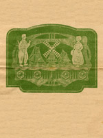
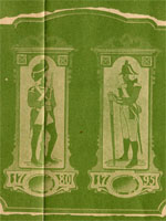
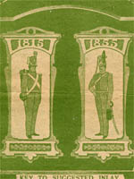
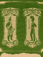
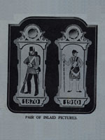 IN continuation of the series of inlaid panels representing the historical uniforms
of the British Army, we bring the pictures up to pre-war period by introducing this
week the dates of 1870 and 1910. The former is the
notable historical date of the Franco-Prussian war, and) although it actually has
no bearing on the costume of the sapper in the Royal Engineers pictured here, the
peculiar cap then worn originated in the Hungarian fur cap. The other picture is of
a Drum Major in the Grenadier Guards, and no plain inlay woods can be made to
illustrate the splendour of this pre-war aristocrat of the army. His ruby
velvet coat was smothered in gold lace, and
the long white gaiters were fastened with buttons from top to bottom. | It is
interesting to note, by the way, that it was the Grenadier
Guards who raised the first band for military purposes, and it is due to them,
probably, that we have such a feast of good music by army bands now. So much
for the pictorial representations ; now for the] building up of the
panels themselves. IN continuation of the series of inlaid panels representing the historical uniforms
of the British Army, we bring the pictures up to pre-war period by introducing this
week the dates of 1870 and 1910. The former is the
notable historical date of the Franco-Prussian war, and) although it actually has
no bearing on the costume of the sapper in the Royal Engineers pictured here, the
peculiar cap then worn originated in the Hungarian fur cap. The other picture is of
a Drum Major in the Grenadier Guards, and no plain inlay woods can be made to
illustrate the splendour of this pre-war aristocrat of the army. His ruby
velvet coat was smothered in gold lace, and
the long white gaiters were fastened with buttons from top to bottom. | It is
interesting to note, by the way, that it was the Grenadier
Guards who raised the first band for military purposes, and it is due to them,
probably, that we have such a feast of good music by army bands now. So much
for the pictorial representations ; now for the] building up of the
panels themselves.
 A Simple Plaque.
The completed articles are roughly the same style as the previous pairs
which have been produced, and form excellent mural decorations for billiard room,
club room, lounge, etc. The panel is composed of a background of mahogany upon
which is the central panel work of the inlaid picture itself . Below and above
the picture is a shaped projecting ledge which serves
to throw the picture itself in greater relief. Below the lower ledge we have the
simple overlay containing the date, whilst at the top of the
picture and above the upper ledge we have an overlay holding in place the small
circular beveled mirror. The general construction, therefore, is simple, as
there are no joints to fix, and all the positions are ruled by the placing of
the one central inlaid panel. A Simple Plaque.
The completed articles are roughly the same style as the previous pairs
which have been produced, and form excellent mural decorations for billiard room,
club room, lounge, etc. The panel is composed of a background of mahogany upon
which is the central panel work of the inlaid picture itself . Below and above
the picture is a shaped projecting ledge which serves
to throw the picture itself in greater relief. Below the lower ledge we have the
simple overlay containing the date, whilst at the top of the
picture and above the upper ledge we have an overlay holding in place the small
circular beveled mirror. The general construction, therefore, is simple, as
there are no joints to fix, and all the positions are ruled by the placing of
the one central inlaid panel.
The General Work.
The first work, then, is to cut out the background from this piece of 3/16-in.
material. Notice in cutting this part that the waste wood along one side serves
to provide the wood for the two shaped ledges. In pasting down the design of the
back, therefore, we can attach to it the parts marked A.A. and when we have cut
out the outline of the backing piece we can proceed to get out the two narrow
ledges. At the top of each back is a circle into which the mirror is fixed later
on, and before cutting it put the actual mirror in place to ensure that the
aperture to be made is large enough to take it. The two ledges, the mirror
overlay, the date overlay, and the small drop ornament beneath the upper
ledge can next be cut, and although there are several pieces, there is not
a great deal of work in any of them. Two of each are required, and we can save
considerable time by cutting them together, because the wood throughout is
1/16-in. thick. Indeed, even with the two boards together it is advisable
to add another piece of wood, say 1/8in. thick so that the thin material
does not split as it is being cut. Care must be taken, too, in cleaning up
these parts with sandpaper, for the 1/16-in. wood is, very likely to break
through in narrow parts unless it is held very firmly and the sandpaper
used on a flat block.
 The Inlay Picture.
There is a considerable amount of work to be • undertaken in the cutting
of the actual inlay pictures, so that it will be a good plan to start work
upon these before cutting out the whole of the various overlays just
mentioned; then, when we get tired of cutting the inlaid parts, we can
put this on one side and cut out one or two of the overlays, returning
again to the inlaid to do a little more. In this way we shall relieve
the tension of continually cutting the inlaid panel and so serve to
make for better work and less impatience. It is, indeed, a good plan to
change our work on any occasion if it is becoming tiring. The small parts
of the inlay demand close and careful attention, and rather than attempt
to rush it and so spoil the result, it is much better to lay the work aside
temporarily and return to it again when we feel more fit. For this reason
the alternate introduction of the work of cutting the overlays will serve
to save time and relieve the monotony. The Inlay Picture.
There is a considerable amount of work to be • undertaken in the cutting
of the actual inlay pictures, so that it will be a good plan to start work
upon these before cutting out the whole of the various overlays just
mentioned; then, when we get tired of cutting the inlaid parts, we can
put this on one side and cut out one or two of the overlays, returning
again to the inlaid to do a little more. In this way we shall relieve
the tension of continually cutting the inlaid panel and so serve to
make for better work and less impatience. It is, indeed, a good plan to
change our work on any occasion if it is becoming tiring. The small parts
of the inlay demand close and careful attention, and rather than attempt
to rush it and so spoil the result, it is much better to lay the work aside
temporarily and return to it again when we feel more fit. For this reason
the alternate introduction of the work of cutting the overlays will serve
to save time and relieve the monotony.
 The Process of Cutting.
The process of inlay cutting has been explained several times previously in connection with these panels, and there
should be now no need to go through the full process again. Roughly, the idea
is that four varieties of wood are used to obtain the colour scheme, and by
nailing them together and cutting the same picture at one operation, the
various parts can be interchanged to form the panel required. The process is a
little longer than the cutting of ordinary fretwork, but as every part of
the wood is used we can make up four distinct panels at one operation.
There is only one of these panels, however, which is really according to
the key given on the Design Sheet, and this has been worked out to get the
best colour scheme out of the material being used. The letters on each part
represent one of the woods we are using, and by fitting the various pieces
together, much as we should a jigsaw, a panel of multicoloured, but very attractive
parts, is made up. The Process of Cutting.
The process of inlay cutting has been explained several times previously in connection with these panels, and there
should be now no need to go through the full process again. Roughly, the idea
is that four varieties of wood are used to obtain the colour scheme, and by
nailing them together and cutting the same picture at one operation, the
various parts can be interchanged to form the panel required. The process is a
little longer than the cutting of ordinary fretwork, but as every part of
the wood is used we can make up four distinct panels at one operation.
There is only one of these panels, however, which is really according to
the key given on the Design Sheet, and this has been worked out to get the
best colour scheme out of the material being used. The letters on each part
represent one of the woods we are using, and by fitting the various pieces
together, much as we should a jigsaw, a panel of multicoloured, but very attractive
parts, is made up.
Cutting and Gluing Hints.
The boards for inlay are only 1/16-in. thick, so that even when four of them
are nailed together the work of cutting is not beyond the ability of the
average worker. Moreover, the result is a perfectly flat panel surface which
lends itself to polishing much more easily than ordinary fretwork. All
the parts are glued in place and a piece of paper added over them, and kept
flat until the glue has set. Then there is the work of cleaning up with
sandpaper until a flat even surface is obtained. If a fine saw is used throughout,
the cutting-line between the various parts will hardly be noticeable, and if a
fine grade of sandpaper is used finally a semi-glossy surface is obtained on
the wood.
The Overlay Positions.
As we mentioned previously, the position of all the overlays is ruled by the
central position of the inlaid panel, so that we must be careful in gluing
this to the back to see that it is in the right place according to the dotted
lines of the design. These dotted lines, of course, will have been cleaned
off the board, but it is advisable before doing that to prick out the corners
of the central overlay in order that we may note the position when that part
is ready to be glued on. The other pieces are fitted up in their order. The
ledge and date are glued up close to the -bottom edge of the panel, but at
the top there is a gap of about 1/8in. between the shaped edge and the smaller
shaped overlay above it. The ledge is fitted close to this overlay, and the
mirror front stand, in turn, on the top of that. It is essential, of course,
that the mirror overlay is exactly in the position to hold the mirror in place,
and perhaps it will be advisable to put this part on first and then glue the
ledge up beneath it, finally adding the overlay above the picture panel.
The mirror is fitted in through
the aperture in the back and held in place either by a backing board or a piece
of card.
Finish with Polish.
There is so little actual fretwork in the completed panels that they lend
themselves very readily to polishing, but if one has not previously had any
experience, the safest plan is to use Hobbies Glaze, applied thinly with a
brush. This will give the whole of the work a
bright appearance, and at the same time provide a good finish quite easily.
|
|
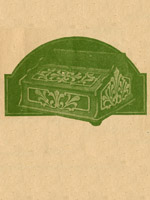
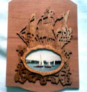
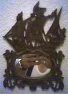
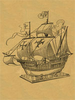
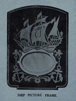 THE two subjects of this week's Design Sheet have been appropriately called '' Old
Ship " Picture Frames. The reason is obvious, and the attractive pieces
of work which can be built quite easily and cheaply will undoubtedly be commenced
immediately by a large number of workers. The picturesque sailing ships of former
days are clearly depicted in the feature work of both frames. In one (that illustrated
on the cover of this issue) we have the broadside view with the bellying sails and the
high stern. In the other (on this page) we have an imaginary picture of the same
vessel but this time looking at it end-on, so getting a view of the stern with its
gun galleries and its lantern braziers above. The broad bottomed shape of the hull—so
different from the present day feather edge keel—allows the placing of an elliptical
opening which serves for the picture or photograph to be placed in.
THE two subjects of this week's Design Sheet have been appropriately called '' Old
Ship " Picture Frames. The reason is obvious, and the attractive pieces
of work which can be built quite easily and cheaply will undoubtedly be commenced
immediately by a large number of workers. The picturesque sailing ships of former
days are clearly depicted in the feature work of both frames. In one (that illustrated
on the cover of this issue) we have the broadside view with the bellying sails and the
high stern. In the other (on this page) we have an imaginary picture of the same
vessel but this time looking at it end-on, so getting a view of the stern with its
gun galleries and its lantern braziers above. The broad bottomed shape of the hull—so
different from the present day feather edge keel—allows the placing of an elliptical
opening which serves for the picture or photograph to be placed in.
A Simple Piece of Work.
Both the frames have additional nautical decorations in the shape of anchors, etc.,
and
both are intended for a postcard picture. Both, too, have the advantage of being quite straightforward, each containing only two pieces of material. Almost any common
fretwood is
suitable, but in view of some of the narrow parts, we would not recommend the use of
open grain boards. Mahogany is supplied by Hobbies, and the two panels mentioned on
the Design Sheet are large enough to carry all the necessary-parts. As both these
panels are 3/16in. thick, all the work will be carried out in these boards, but to
prevent the overlays looking heavy, the inside edge round the glass is beveled down.
The work on both frames is the same, and in each instance we have only a back and a
single overlay. The designs for all four parts are given in full detail on the Design
Sheet, and can, therefore, be pasted direct down to the wood.
Considerations in Cutting.
The work on the back is our first consideration, and we must note that there are
a number of projecting outlines round the outer edge in both instances. For this reason,
the worker
may think it advisable to leave the outline until last, but in any case he should
take away a little of the waste wood, in order to lighten the board which he has
to turn round so often on the cutting-table. The worker may think that this is also
a suitable reason for taking out the ellipse of the glass, but in this instance it
is better to leave this piece until later, as it also serves to bind the whole of
the work together as we proceed with the cutting. The work is quite straightforward,
and our usual remarks apply to the cutting, and in any case we must use a fine saw,
so that we may not have to force it through the wood and so increase the liability
of breaking off some of the narrow parts. It is quite obvious that unless we follow
exactly the lines of the ship, and watch out for the particular placing of the
galleries, the sails, etc., etc., we shall have a very disjointed and, indeed, an
ugly piece of work.
The Ship Feature.
In cutting, watch the whole design carefully and realize that the little piece
which you are then cutting out is merely one small part which helps to form the
complete picture. Watch, too, the wood which is being left, and do not worry
about the exact shape of the piece being cut out. It is what remains that makes
the picture, not the fret of waste wood. A larger picture of the finished boat
may
be useful as you are cutting, and in order that you may have one for reference
by your side, we have given a detail of it herewith. We would recommend the
cutting out of the boat first, and then going on to the anchors, chain and general
ornamentation round the ellipse. Finally, cut out the ellipse itself, having
laid the actual piece of glass upon the design to see that it will go in.
Cleaning Up.
The whole part can now be cleaned up, and we suggest that the centre piece of
the postcard opening be replaced to help to hold the whole part more firmly.
Indeed, it is a good plan to use this piece as a stop, and nail it down to the
bench so that we can sandpaper the rest of the work quite clean while it is being
held firmly.
By the way, when cutting out the elliptical
piece of the frame opening, remember to put the drill-hole actually on the line,
because we shall require this piece of wood as a backing part when we have put
the picture actually in place.
The Overlay. Let us then proceed to the overlay and cut out this corner of the design. In this
instance we are well advised to cut out the central opening first, and to leave
the outside edge until last. This is done in order that we may have a strong board
whilst we are beveling the edge of the overlay where it rests against the glass.
The exact amount of chamfer or bevel is indicated by the section, and this is
undertaken with a long half-round fairly coarse file. Put the work on a cutting-table
and use the file at right-angles to the wood, and with a steady up and down motion.
Do not press too hard or
the file will cut right into the work, probably go too far, and certainly
make ugly gashes. The line of the chamfer is continued evenly round the whole of
the opening. When this has been completed we can carry on with the actual work
of, the part, and finally cut away the waste wood round the outer edge.
Gluing the Parts.
This part, too, has to be cleaned and the same process can be repeated as in the
back. When
the two parts are ready, they can be glued and a piece of board put over the
overlay to ensure it being set flat. Then the glass is put in behind with the
picture immediately after it. Both are held in place by the part cut from the
opening in the back. The edge of the last-mentioned is rounded off, and the part
held in place by the small photo clips obtainable quite cheaply from Hobbies. A
picture of the way in which this is done is shown on the Design Sheet, but if it is
thought that the back projects too far, it is quite a simple matter to fill up the
space behind the picture with a piece of card or two or three thicknesses of
blotting paper. This, in turn, can be covered by a stiff piece of brown paper pasted
down to the back.
|
|
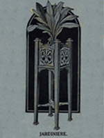 THE introduction of grooved legs makes the building of the Jardiniere illustrated on
this page, a simple matter. Hitherto anything requiring legs has entailed the building
up of corner pieces, or fitting together
various parts to make a suitable and serviceable piece of work. Now, however, we have
introduced a new tapering leg 28 1/2ins. long, at the top end of which is a groove to
take 3/8-in. wood. By using this groove, therefore, to slide in 3/8-in. thick boards,
the opportunity is provided of making up many useful articles of the table type. We
hope, therefore, to publish from time to time various designs in which these legs will
be featured, and which undoubtedly give a more rigid and solid appearance to the work.
No one, at first glance, for instance, would think that the Plant Stand now published
is cut out with the fretsaw ; it looks a piece of furniture made up by a carpenter.
The graceful legs, the strong decorated plant holder at the top, and the general
appearance, all make it such a piece of work as anyone can be proud of. The cost, too,
is well within the range of anybody's pocket, for a complete parcel of mahogany with
the white-
wood necessary for overlays, and including a set of four shaped legs ready to fit,
costs only
9/6. Let us, therefore, obtain the parcel, study the Design Sheet for the parts
concerned, and start straight away with the work.
THE introduction of grooved legs makes the building of the Jardiniere illustrated on
this page, a simple matter. Hitherto anything requiring legs has entailed the building
up of corner pieces, or fitting together
various parts to make a suitable and serviceable piece of work. Now, however, we have
introduced a new tapering leg 28 1/2ins. long, at the top end of which is a groove to
take 3/8-in. wood. By using this groove, therefore, to slide in 3/8-in. thick boards,
the opportunity is provided of making up many useful articles of the table type. We
hope, therefore, to publish from time to time various designs in which these legs will
be featured, and which undoubtedly give a more rigid and solid appearance to the work.
No one, at first glance, for instance, would think that the Plant Stand now published
is cut out with the fretsaw ; it looks a piece of furniture made up by a carpenter.
The graceful legs, the strong decorated plant holder at the top, and the general
appearance, all make it such a piece of work as anyone can be proud of. The cost, too,
is well within the range of anybody's pocket, for a complete parcel of mahogany with
the white-
wood necessary for overlays, and including a set of four shaped legs ready to fit,
costs only
9/6. Let us, therefore, obtain the parcel, study the Design Sheet for the parts
concerned, and start straight away with the work.
The General Plan of Work.
Various small details on the Design Sheet help us to realize how the Stand is
made up. The four sides of the plant-holder are fitted into the grooves of the four
legs, and a floor added beneath the edges. Beneath this floor, in turn, are
little decorative struts, which, in addition, help to hide the end of the grooves
in the legs. Each side of the holder has a single overlay cut from 3/16-in.whitewood,
and as two only of these are shown on the Design Sheet a second one can be bought to
provide the other two, or we can trace them off as usual. At the lower end of the
Plant Stand we have a cross-stretcher with a small ornamental central platform. The
tapered legs come to an end in flattened out feet, whilst at the upper end there is
an ornamental top composed of two shaped pieces of wood. One can see, therefore, that
there is very little actual cutting work to be undertaken, but that the great thing
is to fit the parts together properly to see that they are all glued firmly in
place in order to get a perfectly rigid and strong Jardiniere.
Fixing the Stretcher Piece. A picture of one of the legs is
given herewith, and it will be seen how the side slides into the
groove provided. When these sides are cut they can be tested in the
grooves with the ornamental edge flush with the top. The bottom edge
of each side is flat, and beneath it is cut out and fitted the
floor. This floor has a small piece cut out at each corner in order
to fit round the legs, and having tested all these parts we lay them
aside whilst we proceed with the cutting of the stretcher. This part
has a centre platform with four radial arms. The end of these arms
rests in a notch in each leg, 6ins. from the bottom. This notch merely consists of a straight piece cut through one of the
corners of the leg 3/8in. deep. In marking off the position of this mortise on the
legs,
have all four together in order to ensure that the notch may come level on all
pieces. It should be chiseled out flat and the stretcher tested into each leg.
The Side Overlays.
It is a matter of individual fancy whether the overlays on the sides are fitted
before or after the sides themselves are in place. The best plan probably is
to fit the overlays on before fixing the sides, as this allows a better
grip to hold the two parts together. Cut out the sides, therefore, from their
3/16in. board to the patterns shown, and then glue them in the position indicated
on the side. If one has rubbed off the paper pattern on the side itself,
it is easy to put on the overlays if one remembers that they are Jin. upwards
from the floor of the Stand.
Corner Fillets.
In order to make the Jardiniere thoroughly rigid, triangular fillets are provided
to fit into the right-angle corners of the sides and legs.
These angle fillets are strips 3/8in. wide ready for gluing in place. Eight of these are required 8 1/2ins. long,
and it is advisable to cut them all now so that they are ready when we fit the actual Jardiniere together. All the main pieces of the work are ready for fitting, and our
next process is to assemble them.
Assembling the Parts.
Glue in the four sides of the Stand so that the upper edge is flush with the top of
the leg. A ribbon of glue is laid in the groove itself, and then the board worked
backwards and forwards in the groove slightly to squeeze the glue round the sides
to form a good hold. As these sides are put in we must add the stretcher in the
bottom of the leg, and see that it rests securely in the mortise already tested.
The groove of the leg will hold the sides quite tightly, but let us make sure that
a correct right-angle has been formed by using an angle square or T square. The
placing in of the floor will also serve to strengthen and hold together these parts,
and by turning the Stand upside down carefully we can also screw the floor upwards
to these sides. These screw-holes should have been made previously, for their
position is indicated on the design itself. A good plan to hold the legs until
the glue is set is to tie strong string round them after having padded the corners
with folded newspaper so that the string does not cut the wood. Get the pressure
even with a running knot, and have two pieces, one round the framework of the Stand,
and one over the arms of the stretcher.
Ornamental Caps.
As soon as this grip has been added, put in the corner fillets, as previously
mentioned, and whilst the general framework of the Stand is now left for the glue
to set, we can proceed with the cutting out of the feet and the ornamental tops.
These parts are shown plainly on the Design Sheet, and are simple squares cut from
various thicknesses of wood, and some
with rounded edges. By the time they have been cut and shaped they are ready to
be fitted in place. At the top
of each leg there are two caps and a small toe, the larger cap (piece B) has a
square of wood 2 1/4ins. across with a rounded edge as shown in the section. This
should be glued and screwed down to the top of the leg, and above it the small
square " A " from 1/4-in. wood. The circular No. 20 toe is the final ornament
glued on the top of everything. At the other end of the leg we have two similar
squares—the foot C 1 1/8in. square (which can be tacked as well as glued), and
the lower foot D 1 5/8in.
square. The latter part is cut from fin. wood, and the upper edge is rounded as
can be seen by the section.
The Floor Strips.
The only other parts remaining to be added are the ornamental rails beneath the
floor. These fit between the legs, and are long enough at their ends to cover up
the tapering groove below the floor of the Stand. Before cutting
the ends of the rails, see that they are long enough to fit between the legs
quite tightly, because one can always take off a little if they are actually too
long. The part should be a good fit between the legs and under the floor, and is
held there by glue. In the design a screw is shown through the narrowest part of
this rail, passing upwards into the floor itself, but if a proper fit has been made
there should be no need for this.
Polish to Complete.
The whole Stand being cut in mahogany can be finished off quite well with a coat
of polish, and if this is going to be undertaken it is a wise plan to leave
off the whitewood overlays until their background has been treated with Hobbies'
Lightning Polish.
|
|
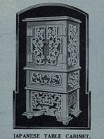 THERE are so many uses to which we could put such a Cabinet as is illustrated herewith,
that it behoves every one of us to start right away on the making of it.
Its usefulness is obvious, and even apart
from this it is quite a pleasing ornament as well as a general receptacle for
the numerous odds and ends which usually accumulate in any room. The height
of the cabinet is 13 1/4ins. when it is raised on the ball feet provided.
The width is 6 3/8ins. and the depth 4ms., thus providing room for a useful
small double door cabinet at the top, and a handy little drawer beneath.
The two doors are hinged with ornamental hinges, and the drawer can be
seen beneath the moulding which runs round all four sides.
THERE are so many uses to which we could put such a Cabinet as is illustrated herewith,
that it behoves every one of us to start right away on the making of it.
Its usefulness is obvious, and even apart
from this it is quite a pleasing ornament as well as a general receptacle for
the numerous odds and ends which usually accumulate in any room. The height
of the cabinet is 13 1/4ins. when it is raised on the ball feet provided.
The width is 6 3/8ins. and the depth 4ms., thus providing room for a useful
small double door cabinet at the top, and a handy little drawer beneath.
The two doors are hinged with ornamental hinges, and the drawer can be
seen beneath the moulding which runs round all four sides.
An Outline of the Construction.
The cabinet is really built in two portions. There
is the upper piece of
the cabinet and drawer, and the lower part which is called the plinth.
These two can be built entirely independently, and are afterwards joined together, as will be explained. We can paste down the
various pieces from the Design Sheet as shown, but must mark off any
duplicates required. Let us begin work upon the upper portion containing
the cabinet
and the drawer. The back and front are shown as one part on the Design Sheet,
but as the back is a plain rectangle 8 5/8ins. long and 5 3/4ins. wide we
can measure off such a piece on to the wood and cut it out straight away.
From the front is cut two doors and the front of the drawer. Put the drill-hole
actually on the cutting-line, and make it as thin as possible, so that when the
part is cut out the starting point cannot be seen. A hole for the knob is
required in each door, and two must also be made in the drawer front for a
similar purpose. The various dotted lines on the design indicate the position
of the overlays, hinges, etc., as well as the runner for the drawer. The only
thing, however, we need mark out is the position of the floor, so that we may
make the screw-holes now to fix this part the easier later on.
The Framework.
The sides of the cabinet are also plain pieces, and these, with the back
and front, are held
beneath a top and bottom board with glue and screws. The top of the cabinet
is shown on the design in the same piece as the top of the plinth—the latter
being really the bottom piece of the cabinet portion. Of the former, both parts
are plain pieces of wood, and we can easily measure off on to boards of the right
thickness the sizes shown for the pieces A & B. In both of them screw-holes
are required, and it will be a good plan to have the two boards held together
so that we may make the screw-holes through both at once. In this way we ensure
the sides being upright when we come to fix them in place. The two sides of the
cabinet are fitted between the back and front, and can now be glued and screwed
together. All screws are counter-sunk, and those at the top
are covered by a smaller piece (top A.) which is cut the same size as the top of
the plinth. The floor of the cabinet is now glued inside, with screws run through
from the back and front to further hold it in place. These screws, in turn, are
covered by four pieces of No. 24 Moulding fitted with the fillet upper-most and
mitred at the corners.
Hanging the Doors.
If we have not previously hinged on the two doors they can be swung now, and
the two small erinoid knobs fixed on to them. To
prevent the door straining inwards, two small stops are provided, and they
are glued inside the cabinet front half-way across so as to hold both doors.
Dotted lines show these positions on the design of the front.
The Drawer. Now we come to the making of the drawer itself,
and the perspective at Pig. 2 should be quite helpful in its
construction. The two ends fit between the back and the front. The
back stands on the floor of the drawer, but the front is glued to
the edge of it, and whilst screws can be added to the former, a
small interior fillet must be glued inside to hold the front to the
floor. This drawer must pass easily through the opening in the front
of the cabinet frame, and slide into place along two runners. Each runner is made up of two pieces— a guide and a runner. The
former serves to hold the drawer straight, whilst the latter, which is glued to it,
forms the floor upon which it slides. The complete piece is shown in detail on the Design Sheet, and is glued to the top of the plinth inside so that the height of the runner is the same height as the opening in the front. If you glance at the design of the front on the Design Sheet, you will see the dotted lines of these parts in position.
Parts of the Plinth.
The various overlays remain to be added to the front and sides. These are all cut
in 1/16in. wood, so that they call for careful manipulation. Before gluing them
in their proper places, have the framework of the cabinet thoroughly cleaned up with
sandpaper. When the overlays are in place, the whole frame can be laid on one side
whilst we prepare the parts for the plinth. This piece comprises all those parts
beneath the bottom of the cabinet portion, and we can, therefore, start to build from
the base upwards, omitting for the present the four ball feet. Two parts go to form
the base itself—base A and base B. The lower and larger base contains the holes for
the feet, whilst on the upper and smaller piece are shown the positions of the
corner moulding and the central overlay C. This corner moulding is supplied slotted
already for the side and front overlays. Do not glue the two bases together, however,
until we have the other parts ready, because the corner moulding has to be screwed
from the underside of the upper base before the base A is fitted beneath it.
The Pillars and Sides.
Let us, therefore, get out the three necessary fretted positions. Note that there
is one also for the back of the plinth to be cut, but the same shape as the outline
only. These four pieces fit exactly into the groove of the moulding, and are
made the same height. When in place, therefore, the top edges of the
moulding and all those fretted pieces, are level, and provide the
support for the cabinet portion previously built up. When this has
been tested, all the parts can be glued together, and then the
moulding screwed to the base B, as previously mentioned. This, with
the addition of base A, completes the work on the plinth itself, and
we can now fix on the cabinet portion. This is glued down securely
to the moulding and top edges of the sides. Further strength is
given by the addition of small fillet strips being glued [along the
inside edge. These can be about 3/16in. or 1/4-in. square glued
along the inner right-angle. Be sure to get
the glue well into these parts, so that the top cabinet portion may be quite rigid
on its plinth. Finally, we can add the wooden ball feet by gluing them up into the holes
previously cut.
|
|
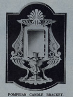 THE subject of our design sheet this week is a striking Candle Bracket illustrated
herewith. It is planned on the Pompeian style of design, and as can be seen by the
introduction of the faun foot and hoof
and the honeysuckle above the mirror, the work is typically Grecian and the rather
severe tracery helps to make up a piece of work which can be cut out without much
labour. Even a cursory glance reveals the fact that there is really little fretwork
to be undertaken, so that the article can be completed quite easily in the course of
one or two evenings. THE subject of our design sheet this week is a striking Candle Bracket illustrated
herewith. It is planned on the Pompeian style of design, and as can be seen by the
introduction of the faun foot and hoof
and the honeysuckle above the mirror, the work is typically Grecian and the rather
severe tracery helps to make up a piece of work which can be cut out without much
labour. Even a cursory glance reveals the fact that there is really little fretwork
to be undertaken, so that the article can be completed quite easily in the course of
one or two evenings.
A Useful Mirror. It
is built up in white-wood, and a beveled mirror is added behind the
candle bracket
to act as a reflector and as an additional piece of artistry. The bracket itself cannot
be clearly seen in the picture because we are looking at the whole thing
absolutely dead on. The bracket, however, which holds the candle
sconce projects by means of a halved shelf about 5 1/2 ins. forward, and reference to
the Design Sheet shows that this bracket is fixed into the back by means of a mortise
and tenon joint. The whole work is quite straightforward and there are few parts to fit
together or to worry us in their construction.
The Largest Piece to Cut.
The main back contains most of the actual fretwork, and is taken out from a piece of
wood 3/16-ins. thick, 12 5/8 ins. long, and 9 3/8 ins. wide. It is advisable in
cutting this to leave the opening for the mirror until last as this will provide us
with a more substantial piece of work to handle in cutting out the frets. In cutting
the mortise joint C we must remember to keep slightly on the inside of the design
lines, and in any case not to make any width greater than 3/16 in. as this is the
thickness of the tenon which has to go into it. The dotted lines on the design of
the back indicate the position of the various overlays and adjoining parts. As, however,
their positions will be quite obvious even on the wood itself, there is no need to
prick out these places, but simply to bear in mind the indications given by the dotted
lines.
Cleaning the Work.
The back, therefore, can be cleaned up straight away. In doing it let us remember
to rub the sandpaper over the reverse side of the wood in order to take off any burr
which has been made by the saw. Pay just as much attention to the cleaning up as you
have done to the cutting, and note that each side of the centreline of the work has
got a definite balance. That is, the spread of the wings, the size of the feathers,
the distance of the long narrow cuts, have all to be the same on each side of the
pattern, so as to maintain a perfect balance in the completed design. It is no use
getting one of the wings considerably larger than the other,
or one of the hoofs more irregular and misshapen than its companion on the opposite
side.
Overlays.
The overlay for the mirror is also cut from 3/16in. wood, and as a plain outline it
can be glued as soon as it is finished and cleaned up, to the back. In order to make
the work easier for handling the overlay of the honeysuckle
which comes above the mirror is cut out as a separate piece, and as it comes from the
same thickness as the overlay itself, the design of the two parts can be pasted down
to the same piece of wood. The pattern of the honeysuckle is shown on the sheet in
the centre of the mirror overlay, and there is no need to cut it from that part. The
complete pattern of the overlay and the honeysuckle can be put down on to one piece
of wood. The honeysuckle pattern is glued to the back so that it stands on the top of
the mirror overlay. This will leave a projection of the honeysuckle over the top of
the back as can be seen by the dotted lines indicating the position on the Design
Sheet.
The Candle Bracket.
Having completed the back, it can be laid on one side whilst we proceed with the
making of the actual bracket which is to hold the candle socket. The forward projecting
piece contains three particular joints about which we must be careful. There is the
tenon C, which we must test out immediately it is cut to see that it fits into the
mortise in the back. There is a small halvings joint at B into which the bracket
stiffener will later be tested, and there is the large square opening into which
the blocks are
to be put to hold the candle socket screw. When the complete piece is cut we can
proceed with the similar pieces which have to be fitted in to the larger one, and
in doing so, carefully test out the joints so that all parts may fit together
tightly. The cross bracket slides up into the halving joint at A, and is there
glued in place. Then we can add the three pieces which form the block to fill
up the square opening in the two parts.
A Solid Block.
This block is composed of three pieces cut
from 3/16in. wood glued together to make a solid piece. Into one end of the edge
of the centre piece is screwed the candle socket and the hole must be made now with
a gimlet before putting the piece actually in place. Glue is applied to the edges
of the bracket
to hold this block, and the top of it
can be shaped slightly concave in order to allow the brass plate of the candle
bracket to rest properly in its place. The small bracket stiffener—which is
also cut from 3/16in. wood—fits into the halving-joint at B and serves to
hold the bracket to give it lateral strength. When the completed bracket has
been built, it can be added into the back with glue along the tenon joint C and
along the back edge.
A Coat of White Polish.
As the whole of the work has been completed in whitewood there is no question
of finish, the surface of the timber being quite good enough to leave in its
natural state. If. however, one prefers to add a polished surface, it can be
easily done by applying Hobbies White Polish over the wood. This can be added
with a brush and does not cover the grain. The article is hung by means of two
wall brackets added to the back, one each side of the honeysuckle design.
|
|
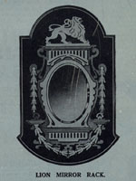 A
SIMPLE but effective Mirror Frame can be made with the Design presented with
this week's issue. A parcel of wood containing all the boards, planed and
cut the required size, costs only 2s. 3d., and the necessary mirror is a further 3s.
The whole
Frame, therefore, can be made up quite cheaply and will form an excel-lent proof
of one's ability at fretwork. The picture herewith gives an idea of the finished
product, and the surmounting lion is an emblem which any worker should be proud
to add to his design. Although they cannot be clearly seen, little projections of
moulding are put on in four places, and these add considerably to the striking
effect of the finished Frame. These pieces of moulding, of course, have returned
ends, and appear above and below the mirror and in two tiny pieces, one on each side.
A further effective piece of ornamentation are the two pendants hanging one on each
side of the mirror. The small pieces of moulding beneath these are put again above a
smaller festoon which passes in
an arc beneath the main overlay on the Frame. A
SIMPLE but effective Mirror Frame can be made with the Design presented with
this week's issue. A parcel of wood containing all the boards, planed and
cut the required size, costs only 2s. 3d., and the necessary mirror is a further 3s.
The whole
Frame, therefore, can be made up quite cheaply and will form an excel-lent proof
of one's ability at fretwork. The picture herewith gives an idea of the finished
product, and the surmounting lion is an emblem which any worker should be proud
to add to his design. Although they cannot be clearly seen, little projections of
moulding are put on in four places, and these add considerably to the striking
effect of the finished Frame. These pieces of moulding, of course, have returned
ends, and appear above and below the mirror and in two tiny pieces, one on each side.
A further effective piece of ornamentation are the two pendants hanging one on each
side of the mirror. The small pieces of moulding beneath these are put again above a
smaller festoon which passes in
an arc beneath the main overlay on the Frame.
Straightforward Work.
The size of the finished piece of work is 16 1/2ins. high and 9 3/4ins. wide, but
throughout the whole
of it there is no work which need frighten even the beginner. The back, as can be
seen by a glance at the Design Sheet, is quite straightforward and contains no
fretwork in the ordinary sense of the word. The only detail work is in the pendants,
festoons and overlays.
but these parts are small and in thin wood. They can, therefore, be -cut quite
easily and without undue loss of time. The back, of course, must come out of a
fairly large piece of wood, but those who have only a 12in. hand-frame will find
they can still do the work if they proceed from each end, passing towards the
centre until the awkward lines are cut.
Saving in Wood.
Workers will note, in pasting down the pattern of the back, that the lion
pediment design is shown in the central aperture of the mirror. This pediment
has to be cut from the same thickness of wood as the back itself so that the
paper pattern may be left untouched and the whole sheet pasted down so that the
lion can be taken out later from the
ellipse to form the opening for the mirror. The same remarks apply to the pendant
overlays at C. & E. These are cut from the waste wood of the mirror overlay,
so that the whole design can be pasted down as one part, exactly as on
the Design Sheet. The other parts, of course, can be pasted on to their various
boards and all of them allowed to dry before we commence work. In the actual
operation of cutting, there is little that calls for definite construction, and
once the fretworker knows how to handle his hand frame and the few other tools
required he should be able to begin and complete the whole of the work in hand.
Overlays as Strengtheners.
So far as the work of cutting the back is concerned, we would advise the worker
to leave the mirror aperture until last. If this is cut out first there is likely
to be a tendency to weaken the wood and so cause it to warp. For this reason, too,
when the part has been completed it is advisable to keep it fixed between two boards
until we are ready to glue on the various overlays. These overlays, by the way, being
glued across the grain, will take out and prevent this tendency in the finished article.
The various dotted lines on the design of the back indicate the several overlays
which have to come on later, but as these are quite obvious in the design itself,
there is little need for us to prick out the positions indicated. Having cut and
cleaned the back, it can be put aside whilst we proceed with the various other and
smaller parts forming the overlays. All of them are cut from 1/8-in. wood, and the
largest is the part which holds the mirror in place on the front. To be effective
this piece must be cut with an accurate ellipse, for when it is in place any
deviation from the cutting-line will show very plainly.
Use a Fine Saw.
The piece which comes out of this centre is used for the cutting of the two
pendants. We must be careful in cutting out these parts not to break off any
of the tender and narrow projections of the design. Indeed, for the cutting of
all these overlays a fine grade fretsaw should be used. Keep it in the hand-frame
or the machine at a good tension, and hold the wood down to the cutting-table as
firmly as possible. If the part " jumps " you are almost sure to break or damage
the delicate fretwork. The cleaning up of these two parts also will call for some
little care. Keep the wood flat on the bench, and the sandpaper flat on its block.
These remarks, too, apply to the overlays at A. & B. which are similar in design,
but cut on a curve in order that they may be fixed beneath the bottom pieces of
moulding on each side of the mirror.
Parallel Cutting.
The two other overlays—above and below the mirror—are most effective because of
their parallel and perpendicular rectangular frets.
Unless these are cut straight and parallel the whole frame will be spoilt.
Although not obtrusive, the very fact of their being parallel to each other
adds dignity and beauty to the Frame. If you cut them so that the lines are
not parallel, but misshapen and awkward, a surprisingly large difference
will be found. We would impress upon some of our readers this very point,
because we have seen some of their work which certainly does not carry out
the advice we so often give in these pages.
Shaping the Moulding.
The position of the moulding is largely wrapped up with the position of the
overlays, so that we should keep all the pieces of moulding required so that
we may glue all the parts down at the same time. The length of the moulding
can be measured off from the design before the paper remains are cleaned off the back.
If you have not already done so here are the measurements. One piece is required
5 3/4ins. long, one piece 5 5/8ins. long, and two pieces 2ins. long. This is the
length after the ends have been returned. The operation of returning has been
dealt with quite recently in these pages. A simple method of returning is to cut
out the end with the fretsaw,, being careful to hold the moulding down to the
cutting-table. Another method is to shape off with a long, flat file, and in
any case the result is the same as we show in the drawing herewith.
The Small Overlays.
Being all ready to glue these overlays and the moulding down, we can first put
in place the large centre-piece round the mirror. Get this firmly in place, and
then fix above it the larger of the two overlays. It is along the top edge of
this that the longest piece of No. 21. moulding is fixed. Beneath the mirror
and 1/8-in. away from the overlay comes the piece of moulding 5 5/8ins, long, and
close up beneath this is the long narrow overlay seen in the illustration of the
finished Frame. On each side of the mirror are the two short pieces of moulding,
and when they are fixed the shaped overlays A & B are glued to the back so that
they meet centrally at the bottom of the Frame. The two straight pendants are
glued on each side.
The Lion Feature.
We have not so far dealt with the lion pediment, and this can be treated entirely
as a separate piece. It is cut from the centre-piece of the mirror, and care must
be taken in cutting it out that the narrow frets forming the mane are not carried
too far to weaken unnecessarily the whole design. When the pediment is complete and
cleaned up, it is glued along the top of the moulding at the top of the Frame.
By referring to the Design Sheet now you can see dotted lines where the base strip
and a piece of the paws is shown on the pattern of the back. When the part is
ready for fixing
there will, of course, be no paper pattern, but the position is obvious. A touch
of glue on the back and the moulding will hold the piece
firmly in place, and because it is thrown forward from the whole of the thickness of
the back the lion stands out in strong
relief and is quite an effective addition to the Frame. |
|